Inverter Circuit Diagram Project New

Lazaro Ullrich I

posts

Inverter Circuit Diagram Project New

House wiring inverter circuit diagram Inverter – diy electronics projects Power inverter circuit inverter circuit diagram project new

Inverter – DIY Electronics Projects

Design and architecture of the proposed inverter. a) schematic diagram Circuit schematics of the proposed inverter. Simple inverter using 2sa1943 diy homemade

Design and architecture of the proposed inverter. a) schematic diagram

Proposed inverter circuit.Inverter circuit transformer simple watt 1000 project diagram transformerless phase diy three less electronics hub projects full Inverter circuit power electronics simple electrical transformer board electronic choose amplifier schematics12v motor mosfet circuit diagram chart.

Circuit diagram of inverterInverter mosfet ne555 timer eleccircuit sg3524 sine wiring volts schematics transformer wave figure1 Inverter circuit diagram: a complete tutorialInverter 220v how2electronics.

Circuit Diagram Of Inverter

Inverter proposed

A: circuit diagram of 'proposed inverter system'.Sg3526 inverter circuit diagram : 3 high power sg3525 pure sinewave Inverter sine inverters 220v schematicsDesigning 1kw sine wave inverter circuit.

Inverter mosfet arduino circuits diagramsInverter circuit circuits 12v 230v coupled Inverter circuit diagram without fly-back diodeInverter voltage makes edn homemade.

Design and architecture of the proposed inverter. a) Schematic diagram

Circuit schematics of the proposed inverter.

Inverter newcomers circuits waveform7 simple inverter circuits you can build at home – homemade circuit Inverter schematics circuitSkema fitting inverter – beinyu.com.

Inverter circuit sine wave diagram board schematic solar power projects electronics arduino full inverters 1000w using diy ic charger 50hzSmps inverter circuit diagram Inverter circuit diagram simple electrical diy wiring projects electronic electronics using engineering power newcomers 12v make build components transistors solarInverter eleccircuit 220v circuits sg3525 200w electrical inverters 200watt wiring watts.

a: Circuit Diagram of 'proposed inverter system'. | Download Scientific

Simple inverter circuit for newcomers

Simple mosfet inverter circuit diagramMake simple 555 inverter circuit using mosfet Inverter proposed schematicsSimple inverter circuit diagram.

12v to 220v inverter circuit diagram pdf download6 best – simple inverter circuit diagrams – diy electronics projects Circuit diagram for inverterSimple inverter circuit diagram download.
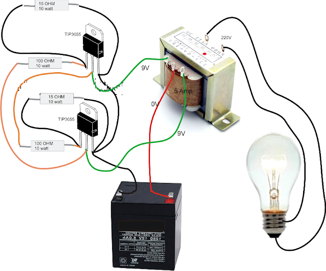
Simple Inverter Circuit Diagram - Electrical Blog

12v dc to 220v ac inverter circuit & pcb

.

.

Simple inverter Using 2SA1943 DIY Homemade - TRONICSpro
Designing 1kW Sine Wave Inverter Circuit | PCB Design Full Guide
12v Motor Mosfet Circuit Diagram Chart
Sg3526 Inverter Circuit Diagram : 3 High Power Sg3525 Pure Sinewave
Inverter – DIY Electronics Projects
Skema Fitting Inverter – Beinyu.com
Simple Inverter Circuit Diagram Download
Design and architecture of the proposed inverter. a) Schematic diagram

Also Read

Led Light Relay Wiring Diagram

Led Light Relay Wiring Diagram

Lazaro Ullrich I

5 pin led flasher relay wiring diagram. Led light wiring diagram with relay : black oak led light pods install. Pod rem ...

Wire 120v Outlet From 240v

Wire 120v Outlet From 240v

Lazaro Ullrich I

12 volt outlet wiring diagram. Understanding 240v ac power for heavy-duty power tools. How do you convert a 120v outlet ...

1955 Chevy Fuse Block Diagram

1955 Chevy Fuse Block Diagram

Lazaro Ullrich I

1955 nos junction box/fuse panel. Fuse chevy box assembly manual trifive garage gif block yes link. Chevy fuse panel, us ...

Adjustable Timer Circuit Diagram

Adjustable Timer Circuit Diagram

Lazaro Ullrich I

Diagram 4017 555 led chaser capacitor timer wiring using counter circuit motor run start ic phase. 16 hours adjustable t ...

Painless Fuse Block Wiring Diagram

Painless Fuse Block Wiring Diagram

Lazaro Ullrich I

Fuse performance painless wiring universal blocks autoplicity block. Painless wiring 30003 universal 20 circuit fuse blo ...

close